


- Home/
- Category/
- Airtac Pneumatic/
- Crossed Roller Way Linear Guide Airtac
/ LGC Series Crossed Roller Way – High Rigidity Precision Linear Guide

LGC Series Crossed Roller Way – High Rigidity Precision Linear Guide
The LGC Series Crossed Roller Way is a high-precision linear guide featuring a non-recirculating crossed roller design for smooth motion, low friction, excellent rigidity, and high load capacity. Available in three-row and four-row configurations, it is ideal for precision machinery, optical measuring equipment, circuit board printers, X-ray systems, and industrial automation applications.
- LGC
- LGC1A
- LGC1B
- LGC2A
- LGC2B
- LGC3A
- LGC3B
- LGC4A
- LGC4B
- LGC6B
- LGC3A200R25-H
- LGC1B20
- LGC1B30
- LGC1B40
- LGC1B50
- LGC1B60
- LGC1B70
- LGC1B80
- LGC2B30
- LGC2B45
- LGC2B60
- LGC2B75
- LGC2B90
- LGC2B105
- LGC2B120
- LGC2B135
- LGC2B150
- LGC2B165
- LGC2B180
- crossed roller way
- crossed roller guide
- precision linear guide
- high rigidity guide
- LGC roller way
Design file download links:
Other fileRAR filePDF fileDescription
Specification:
LGC Series Crossed Roller Way – High-Precision Linear Guide
The LGC Series Crossed Roller Way is a high-precision crossed roller linear guide designed for measuring equipment, precision machinery and industrial automation systems. Its cylindrical rollers are arranged in alternating crossed directions to provide smooth linear motion, high rigidity and stable performance under load.
The product uses a non-recirculating roller design, making it suitable for mechanisms that require a defined stroke, low friction and accurate positioning.
Product Concept
The LGC Series is a linear motion guide consisting of a main rail, side rails and roller cages installed between the guide surfaces. Precision cylindrical rollers are arranged in crossed directions so that loads can be supported from multiple directions.
This configuration provides:
- High structural rigidity within a compact installation space.
- Smooth and accurate linear movement.
- Low friction between the guide surfaces.
- Good multidirectional load capacity.
- Reduced play during direction changes.
- Stable positioning for precision measuring and machining equipment.
LGC Series Construction
According to the supplied product images, the LGC Crossed Roller Way consists of:
- Main rail: the central guiding component of the linear motion system.
- Side rails: retain and guide the roller cages on both sides.
- Roller cage: maintains consistent roller spacing and prevents direct contact between adjacent rollers.
- Cylindrical rollers: arranged in crossed directions to improve rigidity and load distribution.
- End screws: prevent the roller cages from moving out of the rail assembly.
The cylindrical rollers are manufactured with high roundness accuracy and wear resistance according to JIS B 1506 G2 in Japan.
Available Rail Configurations
The LGC Series is available in two structural configurations:
- Type A – Three-row crossed roller way.
- Type B – Four-row crossed roller way.
The three-row configuration offers a compact structure, while the four-row configuration provides a balanced guide assembly with high rigidity for precision linear movement.
According to the ordering information, LGC6 is available only in Type B.
LGC Series Ordering Code
Ordering code example:
LGC3A200R25-H
Code definition:
- LGC: Crossed Roller Way model code.
- 3: Φ3.0 mm roller diameter code.
- A: three-row configuration.
- 200: 200 mm main rail length.
- R25: 25 rollers in each roller cage.
- H: high-accuracy grade.
When the main rail and side rails have different lengths, the rail size may be written as 200 × 100, indicating a 200 mm main rail and 100 mm side rails.
Roller Diameter Codes
The available roller diameter codes are:
- Code 1: Φ1.5 mm roller diameter.
- Code 2: Φ2.0 mm roller diameter.
- Code 3: Φ3.0 mm roller diameter.
- Code 4: Φ4.0 mm roller diameter.
- Code 6: Φ6.0 mm roller diameter.
Larger roller diameters are generally selected for larger guide assemblies and higher load requirements.
Accuracy Grades
Two accuracy grades are shown in the ordering information:
- H – High accuracy.
- P – Precision accuracy.
The appropriate grade should be selected according to the permissible positioning error, repeatability requirement and operating conditions of the machine.
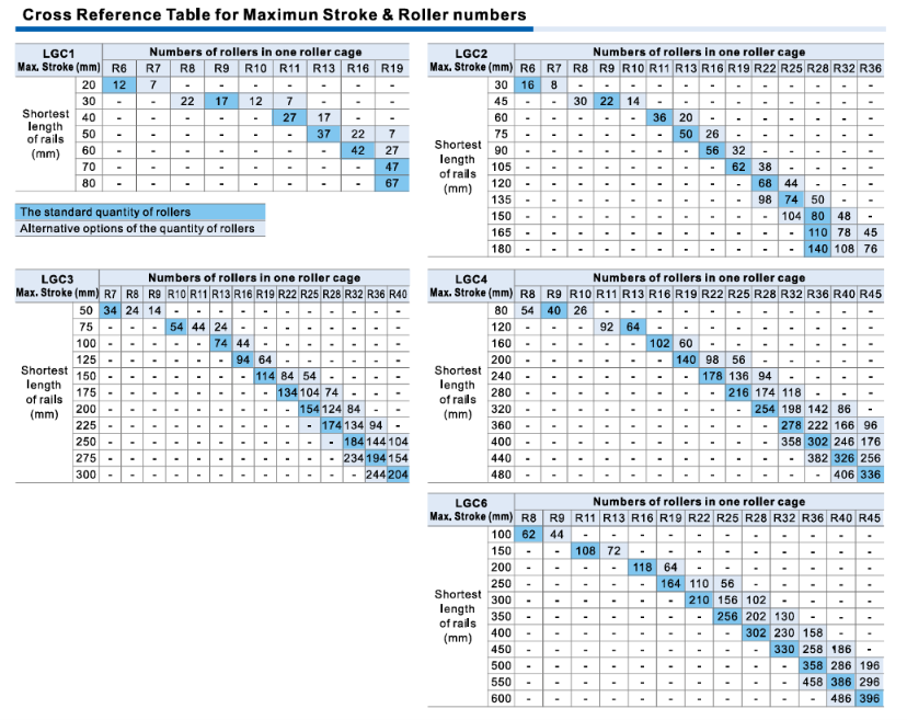
Maximum Stroke Range
According to the cross-reference table for maximum stroke and roller quantities, the available stroke ranges are:
- LGC1: 20–80 mm maximum stroke.
- LGC2: 30–180 mm maximum stroke.
- LGC3: 50–300 mm maximum stroke.
- LGC4: 80–480 mm maximum stroke.
- LGC6: 100–600 mm maximum stroke.
The number of rollers in each cage is selected according to the required stroke and rail length. The table includes both standard roller quantities and alternative roller configurations.
Roller Cage Selection Range
- LGC1: R6 to R19.
- LGC2: R6 to R36.
- LGC3: R7 to R40.
- LGC4: R8 to R45.
- LGC6: R8 to R45.
The R designation identifies the number of rollers in one roller cage. For example, R25 means that each cage contains 25 rollers.
LGC1B Four-Row Model Specifications
Available models:
- LGC1B20
- LGC1B30
- LGC1B40
- LGC1B50
- LGC1B60
- LGC1B70
- LGC1B80
Main dimensions:
- Rail length A: 20–80 mm.
- Dimension B: 8.5 mm.
- Dimension C: 4 mm.
- Diameter DA: Φ3.0 mm.
- Diameter DB: Φ1.55 mm.
- Hole pitch E: 10 mm.
- Dimension F: 5 mm.
- Dimension G: 3.9 mm.
- Dimension H: 1.8 mm.
- Mounting thread J: M2 × 0.4.
- Dimension K: 1.5 mm.
- Dimension S: 1.2 mm.
The n × E mounting-hole arrangement ranges from 1 × 10 for LGC1B20 to 7 × 10 for LGC1B80.
LGC2B Four-Row Model Specifications
Available models:
- LGC2B30
- LGC2B45
- LGC2B60
- LGC2B75
- LGC2B90
- LGC2B105
- LGC2B120
- LGC2B135
- LGC2B150
- LGC2B165
- LGC2B180
Main dimensions:
- Rail length A: 30–180 mm.
- Dimension B: 12 mm.
- Dimension C: 6 mm.
- Diameter DA: Φ4.4 mm.
- Diameter DB: Φ2.5 mm.
- Hole pitch E: 15 mm.
- Dimension F: 7.5 mm.
- Dimension G: 5.5 mm.
- Dimension H: 2.5 mm.
- Mounting thread J: M3 × 0.5.
- Dimension K: 2.1 mm.
- Dimension S: 1.5 mm.
The n × E mounting-hole arrangement ranges from 1 × 15 for LGC2B30 to 11 × 15 for LGC2B180.
Main Features
- Crossed roller arrangement for multidirectional rigidity.
- Non-recirculating roller design for stable movement within a defined stroke.
- Roller cages maintain uniform spacing between cylindrical rollers.
- Rolling contact helps reduce movement resistance.
- Multiple roller diameters and rail lengths are available.
- Three-row and four-row configurations support different machine structures.
- H and P accuracy grades are available.
- Compact dimensions for integration into precision equipment.
- Stroke options from 20 to 600 mm, depending on the selected series.
Product Advantages
- High motion accuracy for positioning and measuring mechanisms.
- Excellent rigidity to minimize deformation under load.
- Smooth movement with low friction.
- Multidirectional load support provided by crossed roller geometry.
- Reduced play during reverse movement.
- Wide selection of rail sizes, roller diameters and roller cage quantities.
- Easy integration into positioning tables, fixtures and linear-motion assemblies.
- Suitable for both compact machines and long-stroke precision equipment.
Applications
The LGC Series Crossed Roller Way is suitable for:
- Printed circuit board printers and PCB production equipment.
- Optical measuring instruments.
- Precision inspection and dimensional measuring machines.
- Industrial and medical X-ray equipment.
- Precision linear positioning tables.
- Machine tools and positioning mechanisms.
- Electronic component inspection equipment.
- Machine vision and camera inspection systems.
- Laboratory instruments.
- Instrument mounting bases and precision fixtures.
- Automatic assembly machines.
- Industrial automation systems requiring stable linear movement.
Selection Guidelines
When selecting an LGC Series Crossed Roller Way, consider:
- Required travel stroke.
- Main rail and side rail lengths.
- Type A three-row or Type B four-row configuration.
- Roller diameter.
- Number of rollers in each roller cage.
- Available mounting space.
- H or P accuracy grade.
- Applied load magnitude and direction.
The selected model should be checked against the corresponding dimensional table and maximum-stroke reference table before ordering.


